With all the cool things that you can do with LEDs today, there is still one thing that’s lacking: simplicity. If you want to run a bunch of LEDs at a time, you usually end up spending a fair bit of time worrying about series and parallel combinations, matching brightness, and picking load resistors. Or, if you’re a beginner, maybe you only get one third of the way through the previous sentence– wondering if you’re already in over your head.
Suppose that you want to make a big LED display for your window or wall: maybe it’s your logo, a symbol, your favorite 8-bit character, or maybe even a sign that spells out words like “OPEN” or “ON AIR.” How do you go about it? The usual DIY solution involves drilling holes in a panel to fit your LEDs, then spending a heck of a lot of time wiring everything up– ending up with one resistor per LED (and a three-dimensional mess if you happen to look at the back side of the panel). And, if you do everything in the most obvious ways, it can even end up consuming a surprising amount of power.
While I have certainly spent my share of time constructing things with the aforementioned technique, at some point it becomes clear that there has to be a better way. In this day and age, shouldn’t LEDs be about as difficult to play with as, say, a Lite Bright? Today we are releasing a new open-source hardware and software design that takes some of the sting, complexity, and mess out of playing with LEDs. It’s a versatile and powerful light-emitting pegboard that lets you efficiently drive hundreds of LEDs in whatever configuration you like, without so much as calculating a single load resistor.

So how does it work?
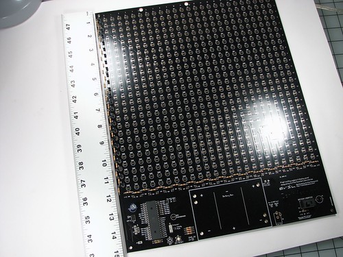
The design is based on a large custom printed circuit board that provides a 25 x 25 grid of locations for LEDs; 625 in all. Around the edges of this array go resistors and transistors that serve to control the array, driven by a large AVR microcontroller. Once those peripheral components around the edges have been added, every one of the 625 LED locations is active, and an LED placed there will light up and be efficiently driven.
Circuit theory
The basic idea is that we have constructed a multiplexed array where only one row of the display is actually turned on at any given time. However, the microcontroller scans through the different rows so quickly that they all appear to be on continuously. The anodes of the LEDs in each column are connected together, and through a single resistor to the positive voltage rail, 4.5 V. Since only one row is ever on at a given time, that column resistor limits the amount of current through just one LED– effectively providing one load resistor for every LED that is on at a given time. The cathodes of the LEDs in each row are connected together and are controlled through a single NPN transistor driven by the microcontroller. This design inherently does not care which LED locations are populated and which are empty– performance is not affected by the number of LEDs in a given row.

Microcontroller
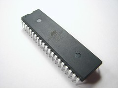
While there are some other ways that the circuit could be driven, we chose to use an ATmega164P microcontroller to drive the display. It is a relatively inexpensive AVR family microcontroller with 16 K of flash, hardly any of which is required for the basic row-scanning functions that we use. The most important thing is that it comes in a 40-pin package that can easily drive the 25 pins of the display and still have room left over for several extra I/O pins including analog to digital converters. One of the main reasons to pick a controller like that is that one of our design goals was for the whole circuit to be seriously hackable. What exactly can be done with that processor and its extra inputs is wide open. As a simple example, our default firmware uses a light sensor and can (optionally) turn off the display during the daytime.
What does it look like?
What does it look like?
First of all it should be stressed that the circuit board is huge: 12 x 15″. That’s because we’ve left enough room at each LED location to fit a “10 mm” LED. The pegboard area itself covers nearly a square foot of space. Immediately below the LED field is room for a battery box (3 x D-cell). On the lower left is the microcontroller and on the lower right there is a place for a power jack and a switch to select whether the board is powered from an adapter or from batteries.
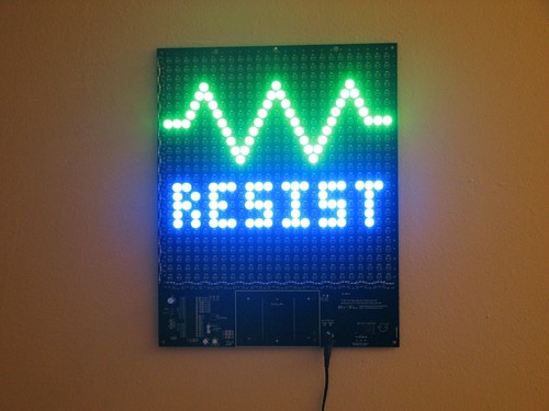
Of course, what we really care about is what it looks like when there are things on the circuit board:


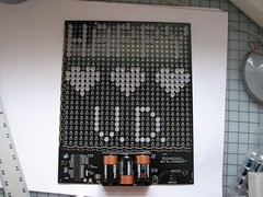
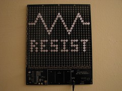

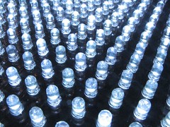

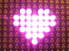
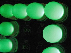
In the examples above, you can see our Evil Mad Scientist “Resist” logo, along with our electronic and sarcastic valentine’s day card. There are also closeups on 10 mm pink, green, and blue diffused LEDs, as well as 5 mm white clear LEDs installed in the panels.
How do you make it?
This project is fully documented, wide open, open source, and you can approach it from any direction you want. Start with the schematics and firmware, or start with a circuit board and a soldering iron. It’s all yours:
- Get a kit here.
- Build instructions and schematics are here (1.7 MB PDF File)
- Download the Bill of Materials (45 kB PDF File), featuring Digi-Key part numbers.
- Thrill at reading the painfully simple GPL-released firmware, written for AVR-GCC. It’s available for download here. (16 kB .ZIP file)
- The circuit board was designed in gEDA PCB, and you can download the original PCB file here; Fundamentally, it’s also source code; we are releasing it under theGPL.
- Want to talk about it? That’s what the forums are for.
FAQ:
1. What’s this all about?
This is an easy way to drive a lot of LEDs– up to 625– in a big matrix. You can make an LED sign for your window, a geeky valentine for your sweetie, one bad-ass birthday card, or freak the holy bejesus out of Boston. Your call. It’s a versatile, high-brightness display.
The display can run off an AC adapter or batteries (3 ‘D’ cells), and is designed to run as many green/blue/white/violet LEDs as you care to solder into the holes, all with excellent brightness. The board can accommodate LEDs in several common sizes: 3mm, 5 mm (standard T-1 3/4 size), and 10 mm. A photosensor is provided that can automatically turn off the display in bright daylight or incandescent light.
The display can run off an AC adapter or batteries (3 ‘D’ cells), and is designed to run as many green/blue/white/violet LEDs as you care to solder into the holes, all with excellent brightness. The board can accommodate LEDs in several common sizes: 3mm, 5 mm (standard T-1 3/4 size), and 10 mm. A photosensor is provided that can automatically turn off the display in bright daylight or incandescent light.
2. Do I have to put the LEDs on the grid, or can I position them exactly where I want to?
You do not have to place every LED on a regular grid. See the instructions for some tips on how to position the LEDs more arbitrarily.
3. What can I reprogram the display to do?
If you have an appropriate interface and like to program, you can control what the display does, either turning all the LEDs on and off, or controlling the individual rows (but not columns) of the display. Here are some basic ideas to get you started:
- Turn on only for a given period of time after it goes dark, or even after a given period of time.
- Blink or flash the whole display slowly or occasionally. Use it as a strobe?
- Add external buttons to control the display.
- Make an insane-o-tv-b-gone? (Yes you can!)
- Use the photosensor to make the display interactive in other ways– turns on for ten seconds when somebody walks by?
- Make an open/closed sign where either the top half or the bottom half of the display is on.
- Make a sign with a static logo in one half and blinking text in the other.
- Animate vertical waves, fading in and out through the display.
- Put different color LEDs in different rows, and alternate how much each of them is driven to make a color changing illumination panel, or a static panel with adjustable color.
- LED coffee table?
- 8-bit style electronic art for your wall or bicycle– it can run on batteries, you know.
- LED illumination panel for photography or even an infrared illumination panel.
- Use the light sensor, or other sensor with the analog inputs and make a scrolling strip chart that records and displays the history of that variable, plotted by the intensity of the rows of the display.
- Attach a sound sensor and make a display or sign that pulses to the beat.
4. What is the “charlieplexing” option/hack?
It’s an alternate configuration (well, a hack, actually) for the board that allows you to control individual LED locations to a limited extent. It requires you to change the hardware around a bit and reprogram the board. It is much dimmer, and doesn’t have enough speed to do anything really complicated. There are also some bugs to work out (A hack with bugs? Never!) that may not make it impossible– or at least very inconvenient– to drive a board that has a lot (note: purposefully left vague) of LEDs on it. So what *can* it do? It can allow very minor animation in limited cases– do you want to blink or wink the eyes on your giant happy face display?
4A. Do you recommend building the multiplexed (standard) or charlieplexed display option?
For almost everyone, the standard option is the way to go. It’s much brighter.
4B. Can I put in 625 LEDs and use this as a full animated display with charlieplexing?
It’s probably possible, but we don’t recommend trying that yet– again, there are some bugs to work out first, and we may need a more severe hack to make it work well.
Eu não posso acreditar nisso. Um grande testemunho que devo compartilhar com todos os pacientes com VÍRUS HERPES SIMPLEX no mundo. Eu nunca acreditei que pudesse haver uma cura completa para o Herpes ou qualquer cura para o herpes, vi testemunhos de pessoas em blogs de como Dr Wealthy prepara fitoterápicos que curam e os trouxe de volta à vida. Tive que experimentar também e não dá para acreditar que em poucas semanas comecei a usar todas as minhas dores pararam aos poucos e tive que sair sem os comprimidos que o médico me deu. Neste momento posso dizer que há poucos meses não tenho tido nenhuma dor, demora no tratamento leva à morte. Aqui está seu e-mail: (wealthylovespell@gmail.com) Whatsapp ele com +2348105150446 visite o blog http://wealthyspellhome.over-blog.com
ReplyDelete